Magnet Design, Engineering & Manufacturing Considerations

- 1.0 Introduction
- 2.0 Modern Magnet Materials
- 3.0 Units of Measure
- 4.0 Design Considerations and Equations
- 5.0 Permanent Magnet Stability
- 6.0 Manufacturing Methods
- 7.0 Physical Characteristics and Machining of Permanent Magnets
- 8.0 Coatings
- 9.0 Assembly Considerations
- 10.0 Magnetization
- 11.0 Measurement and Testing
- 12.0 Handling and Storage
- 13.0 Quick Reference Specification Checklist
1.0 Introduction
Magnets are an important part of our daily lives, serving as essential components in everything from electric motors, loudspeakers, computers, compact disc players, microwave ovens and the family car, to instrumentation, production equipment, and research. Their contribution is often overlooked because they are built into devices and are usually out of sight.
Magnets function as transducers, transforming energy from one form to another, without any permanent loss of their own energy. General categories of permanent magnet functions are:
- Mechanical to Mechanical - attraction and repulsion. Examples of applications that utilize this are magnetic separators, holding devices, magnetic torque drivers and magnetic bearings.
- Mechanical to Electrical - the conversion of motion to electrical energy. Example applications are generators, magnetos, and microphones.
- Electrical to Mechanical - the conversion of electrical energy to motion. Example applications are motors, meters, relays, actuators, loudspeakers, and charged particle deflection, traveling wave tubes, ion pumps, and cyclotrons.
- Mechanical to Heat - the conversion of motion to heat energy. Example applications are eddy current heaters.
- Special Effects - such as magneto resistance, Hall effect devices, and magnetic resonance.
The following sections will provide a brief insight into the design and application of technical permanent magnets. The design & engineering team at Integrated Magnetics will be happy to assist you further in your applications, contact us or send us a request for quote and let us know how we can help.
2.0 Modern Magnet Materials
There are four classes of modern commercialized magnets, each based on their material composition. Within each class is a family of grades with their own magnetic properties. These general classes are:
NdFeB and SmCo are collectively known as rare-earth magnets because they are both composed of materials from the Rare Earth group of elements.
- Neodymium Iron Boron (general composition Nd2Fe14B, often abbreviated to NdFeB) is the most recent commercial addition to the family of modern magnet materials. At room temperatures, NdFeB magnets exhibit the highest properties of all magnet materials.
- Samarium Cobalt is manufactured in two compositions: Sm1Co5 and Sm2Co17 - often referred to as the SmCo 1:5 or SmCo 2:17 types. 2:17 types, with higher Hci values, offer greater inherent stability than the 1:5 types.
- Ferrite, also known as ceramic magnets (general composition BaFe2O3 or SrFe2O3) have been commercialized since the 1950s and continue to be extensively used today due to their low cost. A special form of Ferrite magnet is "Flexible" material, made by bonding Ferrite powder in a flexible binder.
- Alnico magnets (general composition Al-Ni-Co) were commercialized in the 1930s and are still extensively used today.
These materials span a range of properties that accommodate a wide variety of application requirements. The following is intended to give a broad but practical overview of factors that must be considered in selecting the proper material, grade, shape, and size of magnet for a specific application. The chart below shows typical values of the key characteristics for selected grades of various materials for comparison. These values will be discussed in detail in the following sections. top
Table 2.1 Magnet Material Comparisons
|
Material
|
Grade | Br | Hc | Hci | BHmax | Tmax (°C) * |
|
NdFeB
|
39H | 12,800 | 12,300 | 21,000 | 40 | 150 |
|
SmCo
|
26 | 10,500 | 9,200 | 10,000 | 26 | 300 |
|
NdFeB
|
B10N | 6,800 | 5,780 | 10,300 | 10 | 150 |
|
Alnico
|
5 | 12,500 | 640 | 640 | 5.5 | 540 |
|
Ferrite
|
8 | 3,900 | 3,200 | 3,250 | 3.5 | 300 |
|
Flexible
|
1 | 1,600 | 1,370 | 1,380 | 0.6 | 100 |
*Tmax (maximum practical operating temperature) is for reference only. The maximum practical operating temperature of any magnet is dependent on the circuit the magnet is operating in.
3.0 Units of Measure
Three systems of units of measure are common: the cgs (centimeter, gram, second), SI (meter, kilogram, second), and English (inch, pound, second) systems. Here we have used the cgs system for magnetic units, unless otherwise specified. top
Table 3.1 Units of Measure Systems
| Unit | Symbol | cgs System | SI System | English System |
|
Flux
|
Φ | maxwell | weber | maxwell |
|
Flux Density
|
B | gauss | tesla | lines/in2 |
|
Magnetomotive Force
|
F | gilbert | ampere turn | ampere turn |
|
Magnetizing Force
|
H | oersted | ampere turns/m | ampere turns/in |
|
Length
|
L | cm | m | in |
|
Permeability of a vacuum
|
µv | 1 | 0.4π x 10-6 | 3.192 |
Table 3.2 Conversion Factors
|
Multiply
|
By | To obtain |
|
inches
|
2.54 | centimeters |
|
lines/in2
|
0.155 | gauss |
|
lines/in2
|
1.55 x 10⁻⁵ | tesla |
|
gauss
|
6.45 | lines/in2 |
|
gauss
|
0-4 | tesla |
|
gilberts
|
0.79577 | ampere turns |
|
oersteds
|
79.577 | ampere turns/m |
|
ampere turns
|
0.4π | gilberts |
|
ampere turns/in
|
0.495 | oersteds |
|
ampere turns/in
|
39.37 | ampere turns/m |
|
mega gauss oersteds
|
7.91667 | kilo joules/m3 |
Click here for an interactive version of this conversion table. top
4.0 Design Considerations
Basic problems of permanent magnet design revolve around estimating the distribution of magnetic flux in a magnetic circuit, which may include permanent magnets, air gaps, high permeability conduction elements, and electrical currents. Exact solutions of magnetic fields require complex analysis of many factors, although approximate solutions are possible based on certain simplifying assumptions. Obtaining an optimum magnet design often involves experience and tradeoffs. top
4.1 Finite Element Analysis
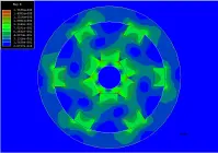
Finite Element Analysis (FEA) modeling programs are used to analyze magnetic problems in order to arrive at more exact solutions, which can then be tested and fine-tuned against a prototype of the magnet structure. Using FEA models flux densities, torques, and forces may be calculated. Results can be output in various forms, including plots of vector magnetic potentials, flux density maps, and flux path plots. The Design & Engineering team at Integrated Magnetics has extensive experience in many types of magnetic designs and is able to assist in the design and execution of FEA models. To learn more, visit our Finite Element Analyses page. top
4.2 The B-H Curve
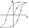
The basis of magnet design is the B-H curve, or hysteresis loop, which characterizes each magnet material. This curve describes the cycling of a magnet in a closed circuit as it is brought to saturation, demagnetized, saturated in the opposite direction, and then demagnetized again under the influence of an external magnetic field.
The second quadrant of the B-H curve, commonly referred to as the "Demagnetization Curve", describes the conditions under which permanent magnets are used in practice. A permanent magnet will have a unique, static operating point if air-gap dimensions are fixed and if any adjacent fields are held constant. Otherwise, the operating point will move about the demagnetization curve, the manner of which must be accounted for in the design of the device.
The three most important characteristics of the B-H curve are the points at which it intersects the B and H axes (at Br - the residual induction - and Hc - the coercive force - respectively), and the point at which the product of B and H are at a maximum (BHmax - the maximum energy product). Br represents the maximum flux the magnet is able to produce under closed circuit conditions. In actual useful operation, permanent magnets can only approach this point. Hc represents the point at which the magnet becomes demagnetized under the influence of an externally applied magnetic field. BHmax represents the point at which the product of B and H, and the energy density of the magnetic field into the air gap surrounding the magnet, is at a maximum. The higher this product, the smaller need be the volume of the magnet. Designs should also account for the variation of the B-H curve with temperature. This effect is more closely examined in the section entitled "Permanent Magnet Stability". top
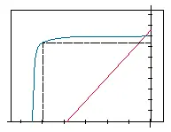
When plotting a B-H curve, the value of B is obtained by measuring the total flux in the magnet (φ) and then dividing this by the magnet pole area (A) to obtain the flux density (B=φ/A). The total flux is composed of the flux produced in the magnet by the magnetizing field (H), and the intrinsic ability of the magnet material to produce more flux due to the orientation of the domains. The flux density of the magnet is therefore composed of two components, one equal to the applied H, and the other created by the intrinsic ability of ferromagnetic materials to produce flux. The intrinsic flux density is given the symbol Bi where total flux B = H + Bi, or, Bi = B - H. In normal operating conditions, no external magnetizing field is present, and the magnet operates in the second quadrant, where H has a negative value. Although strictly negative, H is usually referred to as a positive number, and therefore, in normal practice, Bi = B + H. It is possible to plot an intrinsic as well as a normal B-H curve. The point at which the intrinsic curve crosses the H axis is the intrinsic coercive force, and is given the symbol Hci. High Hci values are an indicator of inherent stability of the magnet material. The normal curve can be derived from the intrinsic curve and vice versa. In practice, if a magnet is operated in a static manner with no external fields present, the normal curve is sufficient for design purposes. When external fields are present, the normal and intrinsic curves are used to determine the changes in the intrinsic properties of the material. top
4.3 Magnet Calculations
In the absence of any coil excitation, the magnet length and pole area may be determined by the following equations:

and

where:
- Bm = the flux density at the operating point,
- Hm = the magnetizing force at the operating point,
- Ag = the air-gap area,
- Lg = the air-gap length,
- Bg = the gap flux density,
- Am = the magnet pole area,
- Lm = the magnet length.
Combining the two equations, the permeance coefficient Pc may be determined as follows:

Strictly,

where µ is the permeability of the medium, and k is a factor which takes account of leakage and reluctance that are functions of the geometry and composition of the magnetic circuit.
(The intrinsic permeance coefficient Pci = Bi/H. Since the normal permeance coefficient Pc = B/H, and B = H + Bi, Pc = (H + Bi)/H or Pc = 1 + Bi/H. Even though the value of H in the second quadrant is actually negative, H is conventionally referred to as a positive number. Taking account of this convention, Pc = 1 - B i /H, or B i /H = Pci = Pc + 1. In other words, the intrinsic permeance coefficient is equal to the normal permeance coefficient plus 1. This is a useful relationship when working on magnet systems that involve the presence of external fields.) top
The permeance coefficient is a useful first order relationship, helpful in pointing towards the appropriate magnet material, and to the approximate dimensions of the magnet. The objective of good magnet design is usually to minimize the required volume of magnet material by operating the magnet at BHmax. The permeance coefficient at which BHmax occurs is given in the Material Properties Charts. top
We can compare the various magnet materials for general characteristics using equation 3 above.
Consider that a particular field is required in a given air-gap, so that the parameters Bg, Hg (air-gap magnetizing force), Ag, and Lg are known.
- Alnico 5 has the ability to provide very high levels of flux density Bm, which is often desirable in high performance electromechanical devices. This is accompanied, however, by a low coercivity Hm, and so some considerable magnet length will be required.
- Alnico 8 operates at a higher magnetizing force, Hm, needing a smaller length Lm, but will yield a lower Bm, and would therefore require a larger magnet area Am.
- Rare Earth Materials offer reasonable to high values of flux density at very high values of magnetizing force. Consequently, very short magnet lengths are needed, and the required volume of this material will be small.
- Ferrite operates at relatively low flux densities, and will therefore need a correspondingly greater pole face area, Am.
The permeance coefficient method using the demagnetization curves allows for initial selection of magnet material, based upon the space available in the device, this determining allowable magnet dimensions. (top)
4.3.1 Calculations of Flux Density on a Magnet's Central Line
Click here to calculate flux density of rectangular or cylindrical magnets in various configurations.
For Magnet Materials with straight-line normal demagnetization curves such as Rare Earths and Ceramics, it is possible to calculate with reasonable accuracy the flux density at a distance X from the pole surface (where X>0) on the magnet's centerline under a variety of conditions.
a. Cylindrical Magnets


Table 4.3.1 shows flux density calculations for a magnet 0.500" in diameter by 0.250" long at a distance of 0.050" from the pole surface, for various materials. Note that you may use any unit of measure for dimensions; since the equation is a ratio of dimensions, the result is the same using any unit system. The resultant flux density is in units of gauss. top
Table 4.3.1 Flux Density vs. Material
| Material and Grade | Residual Flux Density, Br | Flux at distance of 0.050" from surface of magnet |
| Ceramic 1 | 2,200 | 629 |
| Ceramic 5 | 3,950 | 1,130 |
| SmCo 18 | 8,600 | 2,460 |
| SmCo 26 | 10,500 | 3,004 |
| NdFeB 35 | 12,300 | 3,518 |
| NdFeB 42H | 13,300 | 3,804 |
b. Rectangular Magnets

c. For Ring Shaped Magnets
.gif) Equation 6
Equation 6
.gif)
d. For a Magnet on a Steel Back Plate
Substitute 2L in the above formulae.
e. For Identical Magnets Facing Each Other in Attracting Positions
The value of Bx at the gap center is double the value of Bx in case 3. At a point P, Bp is the sum of B(x-p) and B(x-p), where (X+P) and (X-P) substitute for X in case 3. top
f. For Identical, YokedMagnets Facing Each Other in Attracting Position
Substitute 2L for L in case 4, and adopt the same procedure to calculate Bp.
4.3.2 Force Calculations
The attractive force exerted by a magnet to a ferromagnetic material may be calculated by:

Equation 7
where F is the force in pounds, B is the flux density in Kilogauss, and A is the pole area in square inches. Calculating B is a complicated task if it is to be done in a rigorous manner. However, it is possible to approximate the holding force of certain magnets in contact with a piece of steel using the relationship:

Equation 8
where Br is the residual flux density of the material, A is the pole area in square inches, and Lm is the magnetic length.
Click here to Calculate Approximate Pull of a rectangular or disc magnet.
This formula is only intended to give an order of magnitude for the holding force that is available from a magnet with one pole in direct contact with a flat, machined, steel surface. The formula can only be used with straight-line demagnetization curve materials - i.e. for rare earth and ferrite materials - and where the magnet length, Lm, is kept within the bounds of normal, standard magnet configurations. top
5.0 Permanent Magnet Stability
The ability of a permanent magnet to support an external magnetic field results from small magnetic domains "locked" in position by crystal anisotropy within the magnet material. Once established by initial magnetization, these positions are held until acted upon by forces exceeding those that lock the domains. The energy required to disturb the magnetic field produced by a magnet varies for each type of material. Permanent magnets can be produced with extremely high coercive forces (Hc) that will maintain domain alignment in the presence of high external magnetic fields. Stability can be described as the repeated magnetic performance of a material under specific conditions over the life of the magnet.
Factors affecting magnet stability include time, temperature, reluctance changes, adverse fields, radiation, shock, stress, and vibration.
5.1 Time
The effect of time on modern permanent magnets is minimal. Studies have shown that permanent magnets will see changes immediately after magnetization. These changes, known as "magnetic creep", occur as less stable domains are affected by fluctuations in thermal or magnetic energy, even in a thermally stable environment. This variation is reduced as the number of unstable domains decreases. Rare Earth Magnets are not as likely to experience this effect because of their extremely high coercivities. Long-term time versus flux studies have shown that a newly magnetized magnet will lose a minor percent of its flux as a function of age. Over 100,000 hours, these losses are in the range of essentially zero for Samarium Cobalt Materials to less than 3% for Alnico 5 Materials at low permeance coefficients. top
5.2 Temperature
Temperature effects fall into three categories:
- Reversible losses.
- Irreversible but recoverable losses.
- Irreversible & unrecoverable losses.
5.2.1 Reversible Losses
These are losses that are recovered when the magnet returns to its original temperature. Reversible losses cannot be eliminated by magnet stabilization. Reversible losses are described by the Reversible Temperature Coefficients (Tc), shown in table 5.1. Tc is expressed as % per degree Centigrade. These figures vary for specific grades of each material but are representative of the class of material as a whole. It is because the temperature coefficients of Br and Hc are significantly different that the demagnetization curve develops a "knee" at elevated temperatures. top
Table 5.1 Reversible Temperature Coefficients of Br and Hc
| Material | Tc of Br | Tc of Hc |
| NdFeb | -0.12 | -0.6 |
| SmCo | -0.04 | -0.3 |
| Alnico | -0.02 | 0.01 |
| Ceramic | -0.2 | 0.3 |
5.2.2 Irreversible but Recoverable losses
These losses are defined as partial demagnetization of the magnet from exposure to high or low temperatures. These losses are only recoverable by re-magnetization, and are not recovered when the temperature returns to its original value. These losses occur when the operating point of the magnet falls below the knee of the demagnetization curve. An efficient permanent magnet design should have a magnetic circuit in which the magnet operates at a permeance coefficient above the knee of the demagnetization curve at expected elevated temperatures. This will prevent performance variations at elevated temperatures. top
5.2.2 Irreversible and Unrecoverable losses
Metallurgical changes occur in magnets exposed to very high temperatures and are not recoverable by re-magnetization. Table 5.2 shows critical temperatures for the various materials, where:
- Tcurie is the Curie temperature at which the elementary magnetic moments are randomized and the material is demagnetized; and
- Tmax is the maximum practical operating temperatures* for general classes of major materials. Different grades of each material exhibit values differing slightly from the values shown here.
Table 5.2 Critical Temperatures for Various Materials
| Material | Tcurie*°C (°F) | Tmax*°C (°F) |
| Neodymium Iron Boron | 310ºC (590ºF) | 150ºC (302ºF) |
| Samarium Cobalt | 750ºC (0382ºF) | 300ºC (572ºF) |
| Alnico | 860ºC (1580ºF | 540ºC (1004ºF |
| Ceramic | 460ºC (860ºF) | 300ºC (572ºF) |
(*Temperatures are shown in degrees Centigrade with the Fahrenheit equivalent in parentheses.)
*Note that the maximum practical operating temperature is dependent on the operating point of the magnet in the circuit. The higher the operating point on the Demagnetization Curve, the higher the temperature at which the magnet may operate. (top)
Flexible materials are not included in this table since the binders that are used to render the magnet flexible break down before metallurgical changes occur in the magnetic ferrite powder that provides flexible magnets with their magnetic properties. (top)
Partially demagnetizing a magnet by exposure to elevated temperatures in a controlled manner stabilizes the magnet with respect to temperature. The slight reduction in flux density improves a magnet's stability because domains with low commitment to orientation are the first to lose their orientation. A magnet thus stabilized will exhibit constant flux when exposed to equivalent or lesser temperatures. Moreover, a batch of stabilized magnets will exhibit lower variation of flux when compared to each other since the high end of the bell curve which characterizes normal variation will be brought in closer to the rest of the batch. top
5.3 Reluctance Changes
These changes occur when a magnet is subjected to permeance changes such as changes in air gap dimensions during operation. These changes will change the reluctance of the circuit, and may cause the magnet's operating point to fall below the knee of the curve, causing partial and/or irreversible losses. The extents of these losses depend upon the material properties and the extent of the permeance change. Stabilization may be achieved by pre-exposure of the magnet to the expected reluctance changes.
5.4 Adverse Fields
External magnetic fields in repulsion modes will produce a demagnetizing effect on permanent magnets. Rare Earth Magnets with coercive forces exceeding 15 KOe are difficult to affect in this manner. However, Alnico 5, with a coercive force of 640 Oe will encounter magnetic losses in the presence of any magnetic repelling force, including similar magnets. Applications involving Ferrite Magnets with coercive forces of approximately 4KOe should be carefully evaluated in order to assess the effect of external magnetic fields. top
5.5 Radiation
Rare Earth Materials are commonly used in charged particle beam deflection applications, and it is necessary to account for possible radiation effects on magnetic properties. Studies (A.F. Zeller and J.A. Nolen, National Superconducting Cyclotron Laboratory, 09/87, and E.W. Blackmore, TRIUMF, 1985) have shown that SmCo and especially Sm2Co17 withstand radiation 2 to 40 times better than NdFeB materials. SmCo exhibits significant demagnetization when irradiated with a proton beam of 109 to 1010 rads. NdFeB test samples were shown to lose all of their magnetization at a 7 x 10⁷ rads, and 50% at a dose of 4 x 10⁶ rads. In general, it is recommended that magnet materials with high Hci values be used in radiation environments, that they be operated at high permeance coefficients, Pc, and that they be shielded from direct heavy particle irradiation. Stabilization can be achieved by pre-exposure to expected radiation levels. top
5.6 Shock, Stress and Vibration
Below destructive limits, these effects are very minor on modern magnet materials. However, rigid magnet materials are brittle in nature, and can easily be damaged or chipped by improper handling. Samarium Cobalt in particular is a fragile material and special handling precautions must be taken to avoid damage. Thermal shock when Ferrites and Samarium Cobalt Magnets are exposed to high temperature gradients can cause fractures within the material and should be avoided. top
6.0 Manufacturing Methods
Permanent magnets are manufactured by one of the following methods:
- Sintering, (Rare Earths, Ferrites and Alnicos)
- Pressure Bonding or Injection Molding, (Rare Earths and Ferrites)
- Casting, (Alnicos)
- Extruding, (Bonded Neodymium and Flexible)
- Calendaring (Flexible)
The sintering process involves compacting fine powders at high pressure in an aligning magnetic field, then sintering to fuse into a solid shape. After sintering, the magnet shape is rough, and will need to be machined to achieve close tolerances. The intricacy of shapes that can be thus pressed is limited. top
Rare Earth Magnets may be die pressed (with pressure being applied in one direction) or isostatically pressed (with equal pressure being applied in all directions). Isostatically pressed magnets achieve higher magnetic properties than die pressed magnets. The aligning magnetic field for die pressed magnets can be either parallel or perpendicular to the pressing direction. Magnets pressed with the aligning field perpendicular to the pressing direction achieve higher magnetic properties than the parallel pressed form. top

Both Rare Earth and Ferrite Magnets can also be manufactured by pressure bonding or injection molding the magnet powders in a carrier matrix. The density of magnet material in this form is lower than the pure sintered form, yielding lower magnetic properties. However, bonded or injection molded magnets may be made with close tolerances "off-tool" and in relatively intricate shapes.
Alnico is manufactured in a cast or sintered form. Alnicos may be cast in large or complex shapes (such as the common horseshoe), while sintered Alnico Magnets are made in relatively small sizes (normally one ounce or less) and in simple shapes.
Flexible Rare Earth or Ferrite magnets are made by calendering or extruding magnet powders in a flexible carrier matrix such as vinyl. Magnet powder densities and therefore magnetic properties in this form of manufacture are even lower than the bonded or injection molded form. Flexible Magnets are easily cut or punched to shape. Visit our Manufacturing & Assembly page to learn more about our specialty capabilities.
7.0 Physical Characteristics & Machining of Permanent Magnets
Sintered Samarium Cobalt and Ceramic magnets exhibit small cracks within the material that occur during the sintering process. Provided that cracks do not extend more than halfway through a section, they do not normally affect the operation of the magnet. This is also true for small chips that may occur during machining and handling of these magnets, especially on sharp edges. Magnets may be tumbled to break edges: this is done to avoid "feathering" of sharp edges due to the brittle nature of the materials. Tumbling can achieve edge breaks of 0.003" to 0.010". Although Neodymium Iron Boron is relatively tough as compared to Samarium Cobalt and Ceramic, it is still brittle and care must be taken in handling. Because of these inherent material characteristics, it is not advisable to use any permanent magnet material as a structural component of an assembly. top
Rare Earth, Alnico, and Ceramic magnets are machined by grinding, which may considerably affect the magnet cost. Maintaining simple geometries and wide tolerances is therefore desirable from an economic point of view. Rectangular or round sections are preferable to complex shapes. Square holes (even with large radii), and very small holes are difficult to machine and should be avoided. Magnets may be ground to virtually any specified tolerance. However, to reduce costs, tolerances of less than + 0.001" should be avoided if possible.
Cast Alnico Materials exhibit porosity as a natural consequence of the casting process. This may become a problem with small shapes, which are machined out of larger castings. The voids occupy a small portion of the larger casting, but can account for a large portion of the smaller fabricated magnets. This may cause a problem where uniformity or low variation is critical, and it may be advisable either to use a sintered Alnico, or another material. In spite of its slightly lower magnetic properties, sintered Alnico may yield a higher or more uniform net density, resulting in equal or higher net magnetic output. top
In applications where the cosmetic qualities of the magnet are of a concern, special attention should be placed on selecting the appropriate material, since cracks, chips, pores, and voids are common in rigid magnet materials.
Integrated Magnetics has extensive experience in the machining and handling of all permanent magnet materials. Our in-house Machining Facilities allow the ability to deliver prototype to production quantities with short lead times. Contact Us or send us a RFQ and let us know how we can help. top
8.0 Coatings
Samarium Cobalt, Alnico, and Ferrite materials are corrosion resistant, and do not require to be coated against corrosion. Alnico is easily plated for cosmetic qualities, and Ferrites may be coated to seal the surface, which will otherwise be covered by a thick film of ferrite powder (although not a problem for most applications).
Neodymium Iron Boron Magnets are susceptible to corrosion and consideration should be given to the operating environment to determine if coating is necessary. Nickel or tin plating may be used for Neodymium Iron Boron magnets, however the material must be properly prepared and the plating process properly controlled for successful plating. Plating houses experienced in the plating of NdFeB materials are difficult to locate, and must be furnished with the necessary information for proper preparation and control of the process. Aluminum chromate or cadmium chromate vacuum deposition has been successfully tested, with coating thickness as low as 0.0005". Teflon and other organic coatings are relatively inexpensive and have also been successfully tested. A further option for critical applications is to apply two types of protective coatings or to encase the magnet in a stainless steel or other housing to reduce the chances of corrosion. top
9.0 Assembly Considerations
Integrated Magnetics has Manufacturing Capabilities to manufacturer complex magnet pole pieces and housings to provide a complete magnet assembly. The following points should be considered when designing magnet assemblies.
9.1 Affixing Magnets to Housing
Magnets can be successfully affixed to housings using adhesives. Cyanoacrylate adhesives that are rated to temperatures up to 350º F with fast cure times are most commonly used. Fast cure times avoid the need for fixtures to hold the magnets in place while the bond cures. Adhesives with higher temperature ratings are also available, but these require oven curing, and fixturing of the magnets to hold them in place. If magnet assemblies are to be used in a vacuum, potential out-gassing of the adhesives should be considered.
9.2 Housing Design
Integrated Magnetics is equipped with state of the art CNC and EDM equipment allowing the manufacture of complex housings. Effective magnet locating sections should be included in housing designs to support and locate magnets precisely.
9.3 Mechanical Fastening
When arrays of magnets must be assembled, especially when the magnets must be placed in repelling positions, it is very important to consider safety issues. Modern magnet materials such as the Rare Earths are extremely powerful, and when in repulsion they can behave as projectiles if adhesives were to break down. We strongly recommend that in these situations, mechanical fastening be included in the design in addition to adhesives. Potential methods of mechanical retention include encasement, pinning, or strapping the magnets in place with non-magnetic metal components. Our Design Engineering team is experienced in magnet housing and fastening designs, and we will be pleased to assist in helping you arrive at an appropriate design. Contact Us or send us a RFQ and let us know how we can help. top
9.4 Potting
Magnet assemblies may be potted to fill gaps or to cover entire arrays of magnets. Potting compounds cure to hard and durable finishes, and are available to resist a variety of environments, such as elevated temperatures, water flow, etc. When cured, the potting compounds may be machined to provide accurate finished parts.
9.5 Welding
Assemblies that require to be hermetically sealed can be welded using either laser welding (which is not effected by the presence of magnetic fields) or TIG welding (using appropriate shunting elements to reduce the effect of magnetic fields on the weld arc), Special care should be taken when welding magnetic assemblies so that heat dissipation of the weld does not affect the magnets.
10.0 Magnetization
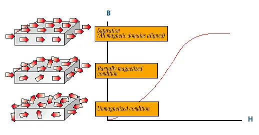
Permanent Magnet Materials are believed to be composed of small regions or "domains" each of which exhibit a net magnetic moment. An unmagnetized magnet will possess domains that are randomly oriented with respect to each other, providing a net magnetic moment of zero. Thus, a magnet when demagnetized is only demagnetized from the observer's point of view. Magnetizing fields serve to align randomly oriented domains to give a net, externally observable field.
10.1 Objective of Magnetization
The objective of magnetization is initially to magnetize a magnet to saturation, even if it will later be slightly demagnetized for stabilization purposes. Saturating the magnet and then demagnetizing it in a controlled manner ensures that the domains with the least commitment to orientation will be the first to lose their orientation, thereby leading to a more stable magnet. Not achieving saturation, on the other hand, leads to orientation of only the most weakly committed domains, hence leading to a less stable magnet.
Anisotropic magnets must be magnetized parallel to the direction of orientation to achieve optimum magnetic properties. Isotropic magnets can be magnetized through any direction with little or no loss of magnetic properties. Slightly higher magnetic properties are obtained in the pressing direction.
10.2 Magnetizing Equipment
Magnetization is accomplished by exposing the magnet to an externally applied magnetic field. This magnetic field may be created by other permanent magnets, or by currently flowing in coils. Using permanent magnets for magnetization is only practical for low coercivity or thin sections of materials. Removal of the magnetized specimen from the permanent magnet magnetizer can be problematic since the field cannot be turned off, and fringing fields may adversely affect the magnetization of the specimen.
The two most common types of magnetizing equipment are the DC and capacitor discharge magnetizers.
10.2.1 DC Magnetizers
DC magnetizers employ large coils through which a current is applied for a short duration by closing a switch. The current flowing through the coil produces a magnetic field, which is usually directed by the use of iron cores and pole pieces, and magnets are placed in the gap between the pole pieces. DC magnetizers are only practical for magnetizing Alnico Materials, which have a low magnetizing force requirement, or small sections of Ferrite Materials.
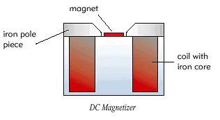
10.2.2 Capacitor Discharge Magnetizers
Capacitor discharge magnetizers employ capacitor banks that are charged, and then discharged through a coil. Provided the coil has a resistance, R, which is greater than

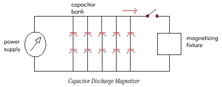
10.3 Saturation Fields Required
Some Rare-Earth magnets require very high magnetizing fields in the 20 to 50 KOe range. These fields are difficult to produce requiring large power supplies in conjunction with carefully designed magnetizing fixtures. Isotropic bonded Neodymium materials require fields in the high 60 KOe range to be fully saturated. However, fields in the 30 KOe range may achieve 98% of saturation. Ceramics require fields in the order of 10 KOe, while Alnicos require fields in the range of 3 KOe for saturation. Because of the ease by which Alnico 5 can become inadvertently demagnetized, it is preferable for this material to be magnetized just prior to or even after final assembly of the magnet into the device. top
10.4 Multiple Pole Magnetization
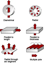
In certain cases, it may be desirable to magnetize a magnet with more than one pole on a single pole surface. This may be accomplished by constructing special magnetizing fixtures. Multiple pole magnetizing fixtures are relatively simple to build for Alnico and Ceramic, but require great care in design and construction for Rare Earth materials.
Magnetizing with multiple poles will sometimes eliminate the need for several discrete magnets, reducing assembly costs, although a cost will be incurred for building an appropriate magnetization fixture. Multiple pole fixtures for Rare Earth magnets may cost several thousands of dollars to build, depending on the size of the magnet, the number of poles required, and the fields necessary to achieve saturation.
10.5 The Orientation Direction

11.0 Measurement & Testing
It is important that incoming inspection of magnetic characteristics be clearly and properly specified. End point characteristics (such as Br or Hc) cannot be directly observed; therefore, inspection personnel should not expect to measure 8,500 Gauss on a SmCo 18 magnet even though the Br is specified at 8,500 Gauss.
A test method or combination of test methods should be based upon the criticality of the requirement, and the cost and ease of performing tests. Ideally, the test results should be able to be directly translated into functional performance of the magnet. A sampling plan should be specified which inspects the parameters which are critical to the application. A brief description of some common test methods follows below.
11.1 B-H Curves
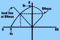
B-H curves may be plotted with the use of a permeameter. These curves completely characterize the magnetic properties of the material at a specific temperature. In order to plot a B-H curve, a sample of the specific size must be used, then cycled through a magnetization/demagnetization cycle. This test is expensive to perform due to the length of time required to complete. The test is destructive to the sample piece in many cases, and is not practical to perform on a large sample of finished magnets. However, when magnets are machined from a larger block, the supplier may be requested to provide B-H curves for the starting raw stock of magnet material. top
11.2 Total Flux
Using a test set up consisting of Helmholtz coil pair connected to a fluxmeter, total flux measurements can be made to obtain total dipole moments, and interpolated to obtain close estimates of Br, Hc, and BHmax. The angle of orientation of the magnet can also be determined using this method. This is a quick and reliable test, and one that is not overly sensitive to magnet placement within the coil.
11.3 Flux Density
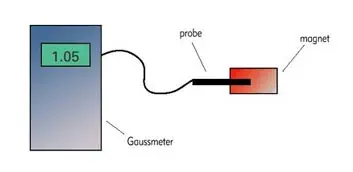
Flux density measurements are made using a gaussmeter and an appropriate probe. The probe contains a Hall Effect device whose voltage output is proportional to the flux density encountered. Two types of probe construction (axial, where the lines of flux traveling parallel to the probe holder, and transverse, where the lines of flux traveling perpendicular to the probe holder, are measured) allow the measurement of flux density of magnets in various configurations. The placement of the probe with respect to the magnet is critical in order to obtain comparable measurements from magnet to magnet. This is accomplished by building a holding fixture for the magnet and probe, so that their positions are fixed relative to each other.
11.4 Flux Maps
Using special scanners equipped with 3- axis Hall probes, magnetic arrays can be mapped, to capture flux densities in x, y, and z directions with a specified number of data points across the entire array. The resulting data can then be output as a flux contour map, as flux vectors, or as a data table for further analysis.
11.5 Pull Tests
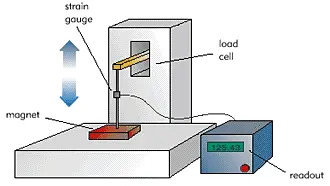
This is a commonly used test for magnets. The pull of a magnet is proportional to B2, and is therefore very sensitive to the value of B. Variations in B occur due to variations in the inherent properties of the magnet itself, as well as environmental effects such as temperature, composition, and condition of the material that the magnet is being tested on, measurement equipment, and operator. Since B decays exponentially from a zero-air gap, small inadvertently introduced air gaps between the magnet and the test material can have a large effect on the measured pull. It is therefore recommended that pull be tested at a positive air gap. Performing pull tests at a number of air gaps and plotting results as air gap vs. ˆš (pull), provides a more accurate description of the pull characteristics of the magnet. Extrapolating from this pull at zero air-gap may be calculated. top
Click here for the on-line MDFA Standard for testing pull of a magnet.
11.6 Other Functional Tests
These should be determined according to the application and after discussion with the supplier. They may involve complex tests such as a profile of flux density along a specified axis, flux uniformity requirements within a defined volume, or relatively simple tests such a torque test.
12.0 Handling & Storage
Please Handle Magnets with Care!
- Personnel wearing pacemakers should not handle magnets.
- Magnets should be kept away from sensitive electronic equipment.
- Modern magnet materials are extremely strong magnetically and somewhat weak mechanically. Any person required to handle magnets should be appropriately trained about the potential dangers of handling magnets. Injury is possible to personnel, and magnets themselves can easily get damaged if allowed to snap towards each other, or if nearby metal objects are allowed to be attracted to the magnets.
- Note that magnets are classified as dangerous goods for air transportation purposes, and strict air shipment rules must be followed for this purpose regarding packaging, labeling and certifications. Click here to learn more.
- Materials with low coercive forces such as Alnico 5 must be carefully handled and stored when received in a magnetized condition. When stored, these magnets should be maintained on a "keeper" which provides a closed loop protecting the magnet from adverse fields. Bringing together like poles in repulsion would lead to irreversible, though re-magnetizable, losses.
- Samarium Cobalt should be carefully handled and stored due to the extremely brittle nature of the material. Click here to learn more about SmCo characteristics.
- Uncoated Neodymium magnets should be stored so as to minimize the risk of corrosion. Click here to learn more about Neo characteristics.
- In general, it is preferable to store magnetized materials under vacuum-sealed film so that the magnets do not collect ferromagnetic dust particles over time, since cleaning this accumulated dust is time consuming.
13.0 Quick Reference Specification Checklist
When requesting design assistance, information should establish adverse conditions to which the magnet may be subjected - for example unusual temperatures, humidity, radiation, demagnetizing fields produced by other parts of the magnetic circuit, etc. The various magnet materials react differently under different environmental conditions, and it is most likely that a material can be selected which will maximize the chances of success, provided that all relevant information is conveyed. top
The following checklist may be helpful in constructing and communicating specifications for permanent magnets:
Material Type
- Nominal, minimum and/or maximum magnetic properties (Br, Hc, Hci, BHmax
- Geometry and tolerances of magnet
- Orientation Direction (and tolerances or orientation direction if critical)
- Whether to be supplied magnetized or not
- Marking requirements
- Coating requirements
- Acceptance tests or performance requirements
- Inspection sampling plan
- Packaging and Identification>
The Design & Engineering team at Integrated Magnetics will be happy to assist you further in your applications, Contact Us or send us a RFQ and let us know how we can help. top


